<assembly.motor />
assembly.motor adds a NEMA stepper motor to an assembly.device. Choose a standard frame or customize the body and shaft with a modelprinter string. The motor has no PCB footprint or schematic symbol.
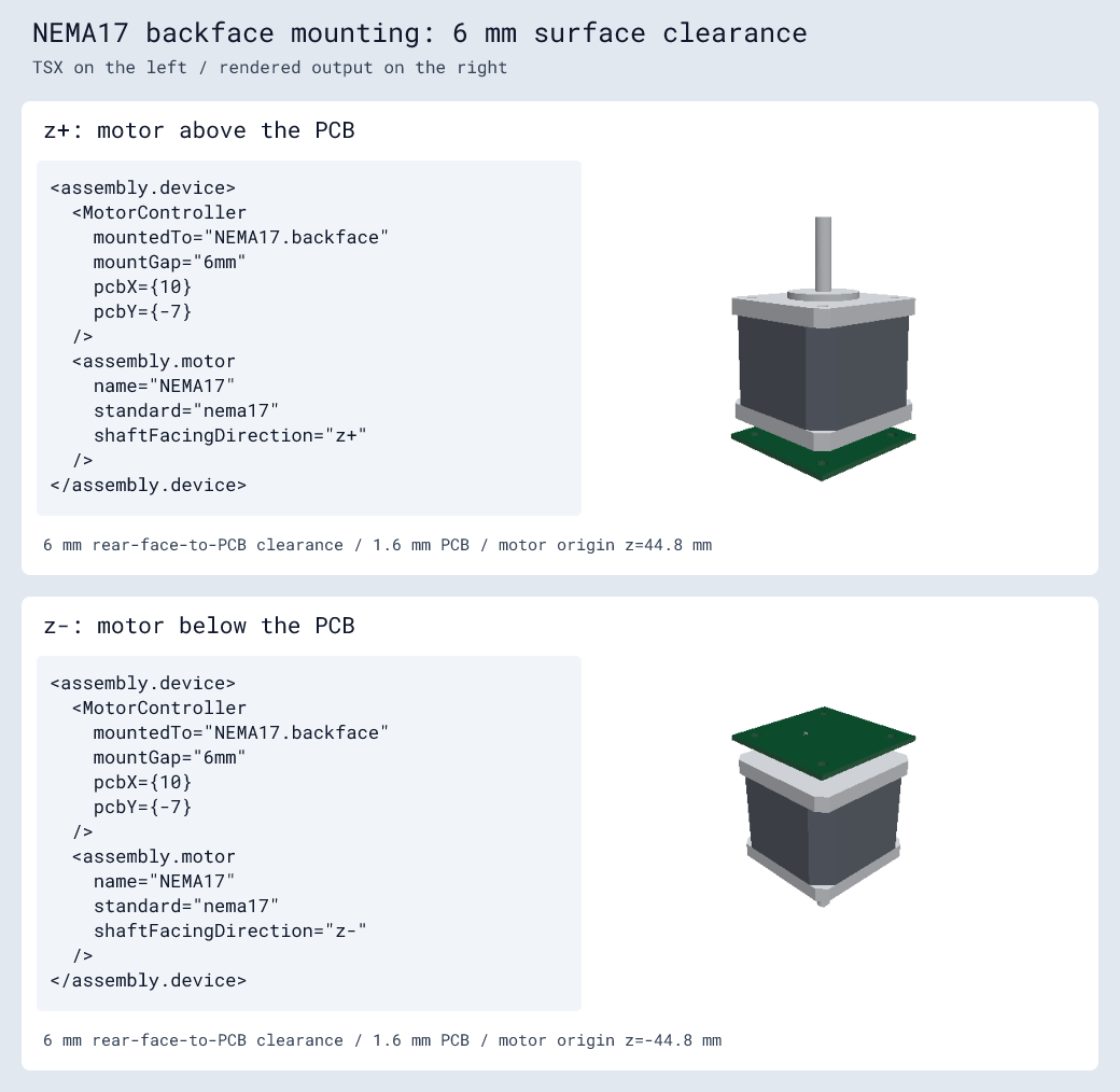
Mount a controller to the motor
Give the motor a name, then set the board's mountedTo to that name followed by .backface. A controller component must forward mountedTo and mountGap to its underlying board, as MotorController does here:
import { assembly } from "@tscircuit/core"
import type { BoardProps } from "@tscircuit/props"

const MotorController = (props: BoardProps) => (
  <board
    width="42mm" height="42mm"
    thickness="1.6mm"
    routingDisabled
    {...props}
  >
    <hole diameter="3.2mm" pcbX={-15.5} pcbY={-15.5} />
    <hole diameter="3.2mm" pcbX={-15.5} pcbY={15.5} />
    <hole diameter="3.2mm" pcbX={15.5} pcbY={-15.5} />
    <hole diameter="3.2mm" pcbX={15.5} pcbY={15.5} />
    {/* Add your controller components and traces here. */}
  </board>
)

export default () => (
<assembly.device>
  <assembly.motor
    name="NEMA17"
    standard="nema17"
    shaftFacingDirection="z-"
  />
  <MotorController
    mountedTo="NEMA17.backface"
    mountGap="6mm"
  />
</assembly.device>
)
backface is the face opposite the shaft. mountGap is the clearance between that face and the nearest PCB surface, rather than the PCB center plane. The example places a 1.6 mm board 6 mm from the motor's rear face, with the shaft pointing below the board.
Mounting keeps the board's PCB layout in the XY plane at Z = 0. The motor follows the board's center and rotation in that plane. Add mounting holes and standoffs yourself; mounting props do not create them. The example's four holes use the default NEMA17 rear-hole spacing of 31 mm.
Motor properties
| Property | Type | Description |
|---|---|---|
name | string | Required motor name, used by board mount references. |
displayName | string | Optional display label. |
standard | "nema8" | "nema17" | "nema23" | Standard modelprinter motor dimensions. Use either standard or model. |
model | string | NEMA modelprinter string for custom dimensions. |
shaftFacingDirection | "x+" | "x-" | "y+" | "y-" | "z+" | "z-" | Optional shaft direction; defaults to "z+". |
Supply exactly one of standard or model. The standard selects representative dimensions; choose a custom model when your motor has a different body or shaft length.
Customize the body and shaft
Use model to specify dimensions without generating or supplying a model URL:
import { assembly } from "@tscircuit/core"

const model =
  "nema17_bodylength38mm_shaftlength24mm" +
  "_flatdepth0.5mm_flatlength15mm"

export default () => (
  <assembly.device>
    <assembly.motor
      name="NEMA17"
      model={model}
      shaftFacingDirection="z-"
    />
  </assembly.device>
)
This model has a 38 mm body, a 24 mm shaft, and a D-flat 0.5 mm deep over the last 15 mm of the shaft. The nema8, nema17, and nema23 standards can all be customized with modelprinter parameters.
Shaft directions and board mounting
Directions use circuit coordinates: +X right, +Y top, and +Z above.
| Direction | Shaft points |
|---|---|
x+, x- | Right, left |
y+, y- | Toward +Y, toward −Y |
z+, z- | Above, below |
All six directions render motor models. Board backface mounting currently supports z+ and z-: the motor is above the PCB for z+, and below it for z-. Mounting a board to a sideways motor reports an error until rotated PCB boards are supported.
| Board property | Type | Description |
|---|---|---|
mountedTo | string | Motor face reference, such as "NEMA17.backface". |
mountGap | string | number | Nonnegative distance in millimetres, such as "6mm" or 6. Defaults to zero when mounted; only meaningful with mountedTo. |
Mount references resolve by exact motor name within the nearest assembly.device, regardless of declaration order. Names in sibling devices remain independent. Missing or duplicate targets, unsupported faces, and multiple boards trying to position one motor report errors.
An unmounted motor's origin is at the world origin on its shaft-side mounting face. Its backface lies one body length behind that face, so changing bodylength also changes the placement needed for a mounted board.